Introduction
During electrical power cuts (load shedding), people use alternative arrangements like rechargeable emergency lamps, solar panels with inverters, battery-inverter systems, and petrol/diesel generators to maintain electricity supply.
Types of Electric Current
Direct Current (DC)
- Definition: Current that flows in a particular direction continuously
- Characteristics:
- Magnitude remains constant over time
- Direction does not change
- Frequency is zero
- Sources: Dry cells, batteries, solar panels (photocells)
- Applications: Mobile phones, computers, and other electronic device internal circuits
- Current-Time Graph: Shows constant magnitude (e.g., 4A) regardless of time
Alternating Current (AC)
- Definition: Current in which magnitude and polarity change continuously at fixed intervals
- Characteristics:
- Direction changes periodically
- Magnitude varies from zero to maximum to zero
- Has frequency measured in Hertz (Hz)
- Frequency in Nepal: 50 Hz (direction changes 100 times per second)
- Voltage in Nepal: 220V to 240V (average)
- Sources: Dynamo, AC generators
- Applications: Fans, motors, refrigerators
- Cycle: One complete variation from zero to maximum to zero to minimum back to zero
Universal Applications
Electric heaters and filament lamps can operate on both AC and DC.
Conversion
Rectifier: Device used to convert alternating current into direct current
Magnetic Effect of Electric Current
Discovery
- Discoverer: Hans Christian Oersted (1820)
- Observation: Magnetic compass needle deflects near an electric circuit
- Conclusion: Electric current produces a magnetic effect
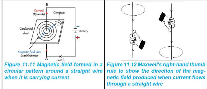
Magnetic Field Around a Straight Wire
- Formation: When current flows through a conducting wire, a circular magnetic field forms around it
- Direction depends on: Direction of current flow
- Pattern: Circular magnetic field lines around the wire
Maxwell's Right-Hand Thumb Rule:
- Grip the wire with right hand
- Thumb points in direction of current
- Fingers indicate direction of magnetic field
- Current upward → Magnetic field anticlockwise
- Current downward → Magnetic field clockwise
Magnetic Field Around a Solenoid
- Solenoid: Cylindrical coil made of insulated wire
- Magnetic Field Pattern: Similar to a bar magnet
- Strong at both ends (poles)
- Weak in the middle
- Uniform inside the solenoid
- Pole Formation: One end becomes North Pole, other becomes South Pole
Maxwell's Right-Hand Grip Rule:
- Grip solenoid with right hand
- Fingers point in direction of current
- Thumb points to North Pole
Factors Affecting Magnetic Field Strength:
- Magnitude of current in solenoid
- Number of turns in the coil
- Material placed inside (core) - soft iron increases strength
Application: Electromagnets (temporary magnetic field)
Magnetic Flux
Definition
Total number of magnetic lines of force passing through a surface area within a magnetic field
Symbol and Unit
- Symbol: Φ (Phi)
- Unit: Weber (Wb) - named after Wilhelm Eduard Weber
Characteristics
- Density indicates magnitude:
- Dense lines → Strong magnetic flux
- Sparse lines → Weak magnetic flux
- Example: Bar magnet has stronger flux at poles than middle
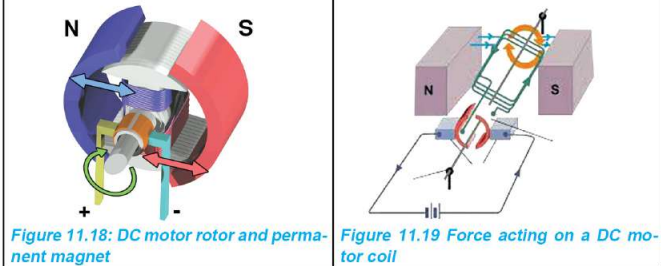
Motor Effect
Definition
Production of motion in a wire placed in a magnetic field when current passes through it
Principle
- Force of attraction and repulsion between two magnetic fields produces motion
- Interaction between permanent magnet field and current-induced magnetic field
Construction
- Coil wound around a core
- Placed between opposite magnetic poles
- AC passed through the coil
- Magnetic field develops and changes direction continuously
- Coil rotates due to field interaction
Methods to Increase Rotation Speed
- Increase number of turns in coil
- Increase surface area of coil
- Use more powerful magnets
- Use soft iron core
Applications
Fans, water pumps, mixer grinders, DC motors
Electromagnetic Induction
Discovery
- Discoverer: Michael Faraday (1831)
- Discovery: Voltage generated when magnetic force lines are cut perpendicularly by a conducting wire
Definition
Process of inducing electromotive force (emf/voltage) in a conductor when there is a change in magnetic flux linked with that conductor
Key Concept
- Moving magnet in/out of coil → Changes magnetic flux → Induces voltage
- Rotating coil in magnetic field → Changes magnetic flux → Induces voltage
- Mechanical energy converts to electrical energy
Faraday's Law of Electromagnetic Induction
Statement: When there is relative motion between a conductor and magnet, an emf is induced in the conductor, and its magnitude is directly proportional to the rate of change of magnetic flux linked with the conductor.
Factors Affecting Induced Voltage
- Strength of magnetic field: Stronger field → More voltage
- Number of turns in coil: More turns → More voltage
- Speed of motion: Faster motion → More voltage (rate of change of flux)
Dynamo and AC Generator
Dynamo
- Use: Small-scale current generation (bicycles, motorcycles)
- Working:
- Magnet rotates near a fixed coil
- Friction between dynamo cap and tire rotates magnet
- Coil cuts magnetic lines of force
- Voltage induced depends on: number of turns, magnetic field strength, rotation speed
AC Generator
- Use: Large-scale electricity production for domestic circuits
- Working Principle: Same as dynamo (electromagnetic induction)
- Construction:
- Rectangular coil in magnetic field
- Coil rotates and cuts magnetic field
- Magnetic flux changes
- EMF induced proportional to rate of change of flux
Large-Scale Electricity Generation
Hydropower Station:
- Water stored in dam flows through tunnel at high pressure
- Rotates turbine at high speed
- Turbine connected to generator produces electricity
Thermal Plant (Coal):
- Coal burnt to produce heat
- Heats water to produce steam
- High-pressure steam rotates turbine
- Generator produces electricity
Diesel Power Plant:
- Diesel engine rotates turbine directly
Wind Power:
- Wind energy rotates turbine
Nuclear Power Plant:
- Heat from nuclear fission of uranium boils water
- Steam rotates turbine
- Not used in Nepal
Nepal's Electricity Capacity (2022 data)
- Hydroelectric potential: 2200 MW
- Thermal plants: 487 MW (Dubahi and Hetauda)
- Under construction: 487 MW
- Proposed projects: 3219 MW (Upper Arun, Uttar Ganga, Dudha Kosi)
Transformer
Definition
Device used to increase or decrease the voltage of alternating current
Principle
Mutual Induction: Inducing emf in a coil by changing current in an adjacent coil
Key Points
- Works ONLY with AC (not DC)
- No mutual induction with DC
- Based on electromagnetic induction
Construction
Components:
- Primary coil: Input coil (receives AC)
- Secondary coil: Output coil (induced AC)
- Core: Laminated soft iron sheets (E, U, I-shaped)
Core Lamination:
- Iron sheets coated with non-conductive paint
- Tied together with nuts and bolts
- Prevents excessive heating from induced currents
Terminology:
- Np: Primary turns (number of windings in primary coil)
- Ns: Secondary turns (number of windings in secondary coil)
- Vp: Primary/input voltage
- Vs: Secondary/output voltage
Transformer Formula
NpNs=VpVs\frac{N_p}{N_s} = \frac{V_p}{V_s}NsNp=VsVp
Types of Transformers
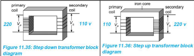
1. Step-Down Transformer
- Function: Reduces voltage
- Construction: Ns < Np (fewer secondary turns)
- Example: If Np:Ns = 2:1, and Vp = 220V, then Vs = 110V
- Applications: Mobile chargers, router adapters, laptop adapters
2. Step-Up Transformer
- Function: Increases voltage
- Construction: Ns > Np (more secondary turns)
- Example: If Np:Ns = 1:2, and Vp = 110V, then Vs = 220V
- Applications: Microwave ovens, power transmission lines
Applications of Transformers
Electricity Distribution System:
- Generation: Electricity produced at power plant
- Transmission: Voltage increased (e.g., 132 kV, 400 kV) using step-up transformer
- Distribution: Voltage reduced (e.g., 220V) using step-down transformer at substations
- Customers: Receive usable voltage
Example: Dhalkebar substation in Dhanusha transmits at 400 kV
Common Devices:
- Mobile charger: 220V → 5.3V
- Microwave oven: 220V → 2100V
- Router adapter: 220V → 12V
- Laptop adapter: Various ratings
Summary Tables
DC vs AC Comparison
FeatureDirect Current (DC)Alternating Current (AC)DirectionConstantChanges periodicallyMagnitudeConstantVaries continuouslyFrequencyZero50 Hz (in Nepal)SourcesBatteries, solar panelsGenerators, dynamosApplicationsElectronicsMotors, appliancesMagnetic Rules Summary
RuleApplicationTechniqueRight-Hand Thumb RuleStraight wireThumb = current, Fingers = fieldRight-Hand Grip RuleSolenoidFingers = current, Thumb = North PoleKey Concepts to Remember
- AC has frequency, DC does not
- Transformers work only with AC, not DC
- Electromagnetic induction converts mechanical energy to electrical energy
- Motor effect converts electrical energy to mechanical energy
- Magnetic flux is proportional to density of magnetic field lines
- Induced voltage depends on rate of change of magnetic flux
- Core lamination in transformers prevents excessive heating
- Nepal uses 50 Hz AC at 220-240V for domestic supply
Gallery
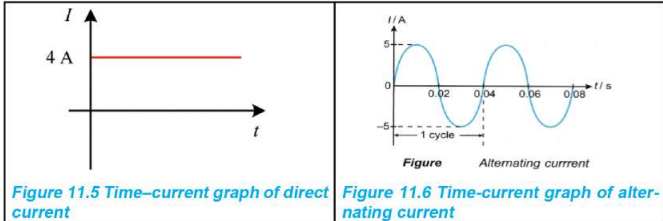
Time Current Graph
Time Current Graph
Maxwell's Righthand thumb rule
Maxwell's Righthand thumb rule
Force acting on a DC motor coil
Force acting on a DC motor coil
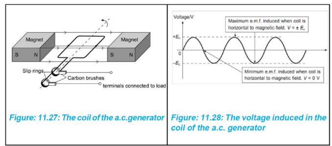
The voltage induced in the coil of the a.c. generator
The voltage induced in the coil of the a.c. generator
Transformer
Transformer